How to Create Spur Gear Involute Gear Profile Help of Autolsip Program in AutoCAD Kindly Help me. Just to be clear you want to draw a helical gear in 2D and not an involute gear.
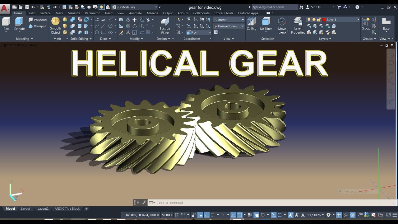
Making 3d Helical Gear In Autocad 2017 Youtube
02 - create a block of one of the teeth butting onto the circle.
. In the Number of Teeth to Draw field enter the number of teeth for the sprocket in order to calculate the diameter of the pitch circle. In other words at 0 90 180 or 270 degrees. How do you make a helical gear in AutoCAD.
Specify the height of the helix. With a shared sketch it will take fewer steps than on the video. If you want 15 deg just enter 15360 in the revolution field.
Academiaedu is a platform for academics to share research papers. Specify the top radius or press Enter to specify the same value as the base radius. Make two arcs like this one for cutting teeth.
2422 Double helical gears. In the Select Part Size dialog box select the size of the chain. Tutorial Making a helical gear in AutoCAD.
With help of Autolsip Program. Up to 24 cash back How to draw helical gear in autocad 2d 1. It will show the boundary creation dialogue.
Inputs tab Specifies the properties of the gear wheel and the loads acting on it. Use revolution and height that way you set the gear thickness at the same time. Select the Library button.
1 I have Gear teeth Cutter Details Gear Blank Before Machining Details Now i want to Create Gear Profile. May 2nd 2018 - autocad how to draw spur gear tooth profile drawing i want to draw helical gear in autocad 2010 how to draw helical gear tooth frofile in autocad module 2 gears nptel may 13th 2018 - module 2 gears lecture 17 in a turbine drive 300 kw power is transmitted using a pair of double helical gear gear. You can easily model a helical gear in the part environment just use the coil feature.
2 Draw a line 120th of the Base Circle Radius RB long FCB 03025 at a right angle from the end of that line. Make two arcs like this one for cutting teeth. Now the tutorial How to Making a helical gear in AutoCAD has been finished.
Rest of Torque on Shaft Specifies that the selected torque compensates for the imbalance of torques acting on the shaft. Make a circle of 35mm radius at center. Trim the circles side ways.
Note that a right-hand helix engages with a left-hand helix and the hand of the helix must be correctly stated on the drawing. Make the profile of the gear tooth spaces. But there is just isntat least i cant find any information like that i mean step by step how to draw an accurate involute for a helical tooth.
Trim down the circles. 1 Draw a line from the circle center 00 to the base circle perpendicular to your grid. Click inside the region and then press enter.
Gear Load Specifies the load applied on or by the gear wheel. On both gears the helix angle will be the same. Make another circle of 50mm concentric to previous one.
Make a circle of 35mm radius at center. 03 - divide the circle by this block by the number of teeth you require. Specify the base radius.
Make another circle of 50mm concentric to previous one. This will automaitcally create the teeth for you around the circle you originally created. Libro de diseño de máquinas de Shigley.
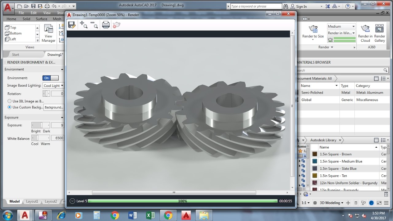
2 This Method is Very Accuracy Kindly Help Me. This is an easy tutorial on how to model a Helical Gear using AUTOCAD by using SWEEP COMMANDHelicalGearAutocadMechanicalAC3dCADThe Unit for this drawing. How do you make a helical gear in AutoCAD.
This is from the book i have on gears but it shows how to draw an accurate involute gear tooth not a helical gear and it is quite easy. Email protected email protected. This video how to Designing a helical Gear with AutoCAD.
Make a circle of 50mm radius. I had problems with this because at step 13 were suppose to type in a radius value of 035 which I kept thinking was actually 035 notice the period not comma. 01 - to draw the circle of your gear.
Hole and Thread Note 2. Helical Gear Autocad Design In English Youtube Making 3d Helical Gear In Autocad Youtube Basic Tutorial Designing A Helical Gear Youtube. How do you make a helical gear in AutoCAD.
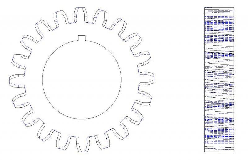
Specify the center point for the base of the helix. Helical gear drawing 1. How to draw helical gear in autocad New and latest designs are now being introduced by specialists so A growing number of women can follow the streak of nail artworkNow I am unfolding before you.
In the Select a Chain dialog box select the type of the chain. If you need any tutorial to improve your skill in autocad please visit other tutorial on this blog. Use the Gear dialog box to define the torque delivered by a spur gear wheel helical gear wheel or bevel gear wheel.
Trim down the circles. How To Draw Helical Gear In Autocad. Subtract the arrayed sweeps from the cylindrical body and we have the helical gear created.
Help with sculpt 1. Now we have the polyline created. Right click on the screen and select multiple.
How to draw 2D helical gear drawing in Autocadshock. A On same wheel b On separate wheels. I chose 270 degrees.
This video how to Designing a helical Gear with AutoCAD. Now enter bo command. Where shafts lie parallel to each other the helix angle is generally 15-30.
Click Home tab Draw panel Helix. Tutorial on making helical gear in AutoCAD 2011.
Helical Gear Student Project Questions Autocad Forums
Making 3d Helical Gear By Sweep Twist Command Autocad 2017 Youtube

Making 3d Helical Gear In Autocad Youtube
Helical Gear Autocad Design In English Youtube

Auto Cad Tutorial 6 How To Draw A Herringbone Gear In Auto Cad Youtube

Basic Tutorial Designing A Helical Gear Youtube

Autocad 3d Modeling Tutorial How To Make Helical Gear In Autocad 2017 Youtube

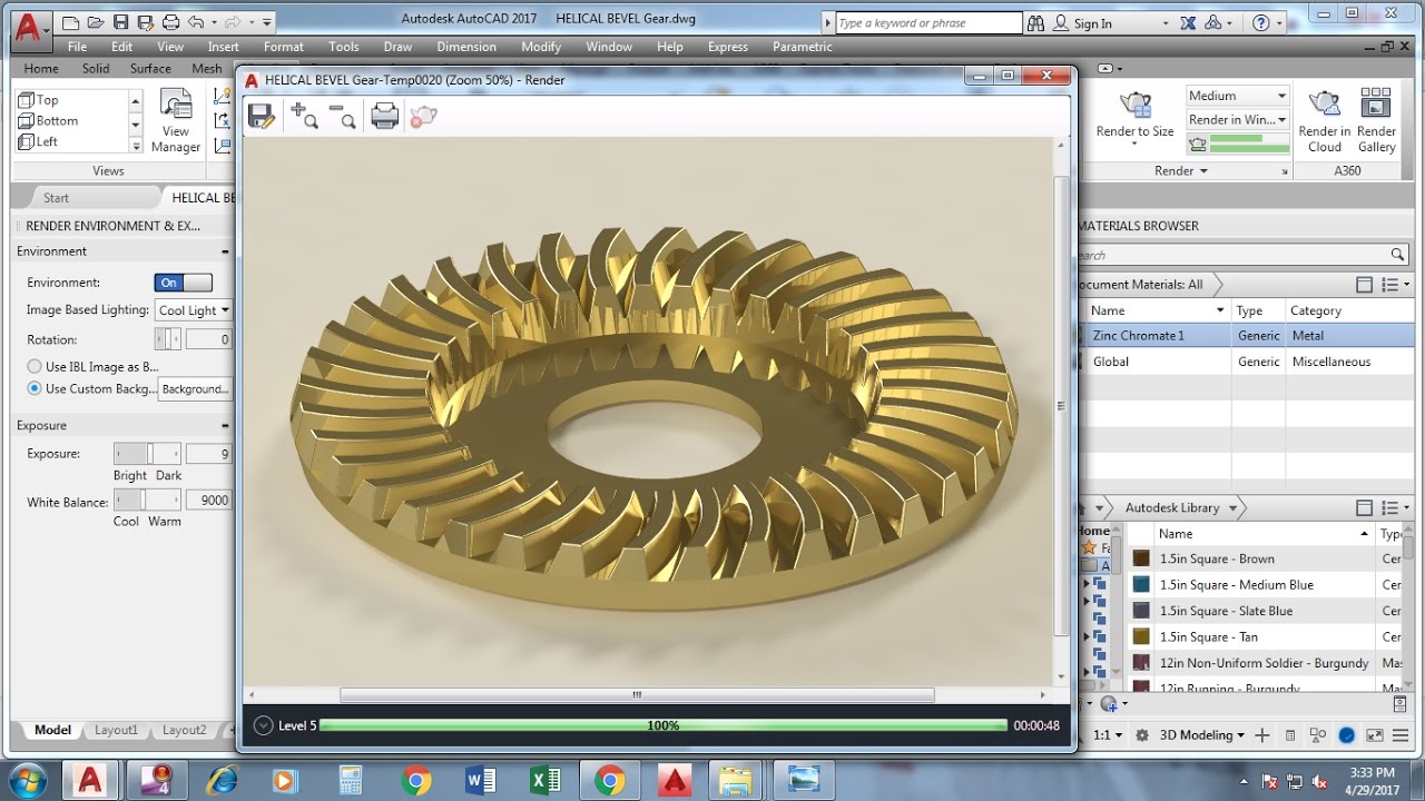
Making Helical Bevel Gear In Autocad Autocad 3d Modeling Practice 3d Cad Model Library Grabcad
0 comments
Post a Comment