Please do suggest on the same. Sample sizing calculations for BFW pumps and Fans for a typical Coal fired Boiler generating steam of 50000 Kghr at 67 kgcm2 and 485 degC.
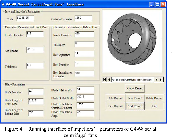
Figure 4 From A Digital Design Method Of Geometric Model For Centrifugal Fan Impeller Based On Solidworks And Vb Semantic Scholar
Fan Data RPM Motor Sheave Dia Fan Calculation authored and generated by CTC Design Inc.
. The fan calculator addresses only the blade angles. No cooling system is needed due to small. Tst The static pressure P of the fan-Is the total pressure P diminished by the tf.
Use only and is not to be used by others without written. Pneumatic conveying and other industrial process work Head Calculations 1 2 suction discharge For a fan Z 0. The head losses generated by the blade tip angles inlet and outlet define a.
Furnace pressure oscillates - 05 and that equates to a speed swing of about - 10-15. Effect of axial gap between inlet nozzle and impeller on efficiency and flow pattern in centrifugal fans numerical and experimental analysis. The highest efficiency of all of the centrifugal fans.
The Induced Draft ID fans and Forced Draft FD fans provide control for draft and forced air zoning of fuel burned furnaces of steam generation plant of a thermal power plant. Fans are in parallel. The power output of a fan-Is expressed in kilowatts and is based on fanvolume and fan total pressure.
Induced Draft ID Fan is used to draw the flue gases from the system generated from the combustion of fuel. 9 to 16 blades of airfoil curved away from the direction of rotation. Centrifugal Fan Design Calculations Pdf.
0 replies 203 views. 110000 lbhr at 950 PSI 905 F. PE 0 and Q 0 because fans are designed to overcome fluid friction.
Fan aerodynamic performance at the design point requires air at a temperature of 267C an impeller shaft speed of 1692 rpm and a shaft power of 12766 kW 2 PWR ref to produce a lift static pressure of 7517 Pa 𝑃 ref at a nominal lift-side air flow rate of 5743 m 3 s. We are controlling fan speed with a variable frequency drive. Static Pressure vs Fan speed CTC Design Inc.
This file and its content is the exclusive property of CTC Design Inc. Suitable for higher static pressure up to 14 35 KPa. The drive is doing what the control system is demanding which is trying to control the furnace pressure -05.
This projects aim is to analyse the ID fan lubrication system and then. Motor power required for its working depends upon the following factors-. New Ideas for Future Research FD Fan Duct APH Duct Furnace Duct APH Back pass ESP ID Fan Chimney Duct Duct Analysis of Flue Gas at the ID Fan Inlet Partial pressure of each constituent in flue gas pCO2 16366209 kPa pO2 1138404 kPa PN2 68142138 kPa pSO2 0036081 kPa pH2O 13363218 kPa Mass flow rate of each constituent in tonshour.
Power required for ID Fan BHP Flow x Head Efficiency x 758. Standard conditions are considered to be 70 degrees Fahrenheit with an elevation of zero feet sea level and an inlet pressure of zero inches of water column giving a density of 0075 pounds per. Motor power required for its working depends upon the following factors-ID Fan Capacity Quantity of flue gases drawn from the system measured in m3Hr.
Axial fans as the name implies move an airstream along the axis of the fan. Online Induced Draft ID Fan Motor Power Calculator. The static efficiency of a fan-Is the mechanical efficiency multiplied by theratio of the static pressure to the total pressure or e e PP.
FD Fan Capacity Quantity of air forced through the fan measured in m3Hr. The ID fan exhausts flue gases from the furnace and induces combustion air into the furnace by having the furnace operated under negative pressure. Forced Draft FD Fan is used to deliver the high-pressure air of desired quantity for the combustion of fuel.
20 Mar 2022 Three Phase Condenser Design. The primary control is for furnace pressure on a boiler. The highest speed of the centrifugal fans.
Use a safety factor of Sf 2 Required airflow will be 380 CFM 108 m3min. Online FD Fan Motor Power Calculator. Ad AirPro builds heavy-duty high-temp industrial fans for induced draft applications.
Baffled Jacket For Vessel Design Choices Started by Guest_HWIK_ 20 Mar 2022. Forced Draft FD fans are used for. Fan total pressure FTP is the increase in total pressure pt measured by facing pitot tubes across the fan FTP pt2 pt1 101 Fan velocity pressure FVP is the average velocity pressure at the fan outlet only pv2 pt2 - ps2.
Applicable Fans Based on the air flow requirement the MRS18-BTMis the best match. The air is pressurized by the aerodynamic lift generated by the fan blades much like a propeller and an airplane wing. About Steam boiler steam and drawing thermodynamics steam table Know about some things Boiler Math solution Energy conservation thermodynamic therma.
Consequently these issues have caused half-load unit 225 MW run-backs and full unit 450 MW trips over the past decade. ID Fan Design Calculations- Equations. 190 CFM 54 m3min.
The sweet spot is when the inlet diameter of. Search for the cross point B between the parallel line and surface area S 242 m23758 in2 line. Books On Idfd Fan Design Calculations - posted in Industrial Professionals.
Mechanicalelectrical efficiency must be dealt with by the designer when selecting suitable materials and drive systems. ID Fan Motor Power Calculator. That being said you need to do some extra calculations with non-standard conditions as they can have a big impact on your fan sizing and design.
Let us assume Fan efficiency as 75 and Motor Efficiency as 90. Draw a line parallel with the x axis from point A. Feed Water inlet at 105 C and Exhaust gas temp at 150 C.
Sizing calculations of Boiler Pumps and ID FD Fans. The ID fan problems have arisen from the bearing lubrication system which provides oil recirculation to the induction motor bearings and fan main shaft bearings. Learn more and request a free quote for your induced fan application.
Its intended for CTC Design Inc. Although they can sometimes be used interchange-ably with centrifugal fans axial fans are commonly used in clean air low-pressure high-volume. Approximate 250 mmWC Taking 20 margin on head ID Fan head 250 12 300 mm WC Power requirements of ID Fan.
Centrifugal Fan Design Odologies Centrifugal fan design odologies numerical and experimental study of centrifugal fan flow design of a three dimensional centrifugal fan with controlled design calculation of single stage radial type centrifugal er. ID Fan static Head Draft Loss in Boiler Duct Dust collector 150 50 50 mm WC. Deep blades for efficient expansion with the blade passages.
FD Fan Head Air pressure required to overcome the losses during traveling. Whats people lookup in this blog.

Centrifugal Fan Capacity Calculation In English How To Calculate Fan Capacity Centrifugal Fan Youtube

Pdf Design Calculation Of Single Stage Radial Type Centrifugal Blower For Rice Mill Semantic Scholar

Figure 4 From A Digital Design Method Of Geometric Model For Centrifugal Fan Impeller Based On Solidworks And Vb Semantic Scholar

Alumina Technology Ceti Enterprises Design Of F D Fan And I D Fan For Calciners In Alumina Refinery
2
Centrifugal Fan Design Calculations Xls Solution By Surferpix
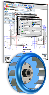
Axial And Centrifugal Fan Software Ciclo Software
Software For The Design Of Fans Blowers
0 comments
Post a Comment